SLM smart LED load module Installation Instructions
To install a Gambeks SLM smart LED load module as a replacement for standard load resistors in automotive LED turn signal circuits, follow these steps. The SLM module is engineered for direct integration, offering easy installation, error correction, and no heat dissipation requirements
Smart Led Load module models list:
Gambeks SLM Smart LED Load modules offer innovative, non-heated electronic solutions that simulate the electrical load required for proper vehicle system operation after retrofitting incandescent bulbs with LEDs. These modules are designed to replace traditional load resistors completely and address CANbus errors, hyper flashing, and correct LED failure detection.
1. SLM42124 – 4 way 21W 24V, replaces 4 standard LED Load resistors
2. SLM22124 – 2 way 21W 24V, replaces 2 standard LED Load resistors
3. SLM22112 – 2 way 21W 12V, replaces 2 standard LED Load resistors
4. SLM42112 – 4 way 21W 12V, replaces 4 standard LED Load resistors
Included in the SLM kits:
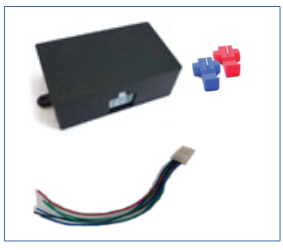
Smart Led Load module- 2 way
- Smart Led Load module-2 way – 1 pcs
- Electrical quick connects – 2 pcs
- Cable assembly for connection for 6 pin– 1 pcs
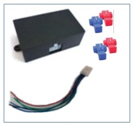
Smart Led Load module- 4 way
- Smart Led Load module-4 way – 1 pcs
- Electrical quick connects – 4 pcs
- Cable assembly for connection for 10 pin – 1 pcs
Caution
These instructions assume technical knowledge/experience in automotive repair. If you are unfamiliar with the basics of auto repair, please seek professional help
to install this update. These instructions are not a substitute for good practice or common sense. Improper repairs may result in property damage or injury.
Required tools and supplies:
• Voltmeter or digital multimeter (DMM);
• Pliers;
• Electrical tape;
• Self-tapping screws and/or cable ties as needed.
You will need one SML 2 – way module for the front pair of LED turn signals ( left and right) , or SML 4 – way module if you want to replace the front pair and rear pair of LED turn signals.
The SML modules is installed in series (end to end) in the light circuit not in parallel (across the circuit) as regular led load resisor.
The SML modules can be used on an LED bulb, or an LED lamp assembly 21W power.
The modules connecting a 2-channel or 4-channel SLM module to the vehicle’s power supply, it is necessary to connect the + power wire to a separate fuse on the vehicle’s power panel.
Note! If the lights are turned on when checking, be sure to turn them off before installation.
Step 1:
With the device powered off, locate the LED power wires where the SML will be connected.
• Do not cut the wire.
• Make sure there is enough space to install the quick connector.
Step 2:
First of all, connect the module power wires to the vehicle power supply through a fuse.
Cut the turn signal power wire right or left turn signal in any order and using quick-connect connectors, connect one end of the wire to the module’s IN1 and the other end to the module’s OUT1 and the wires of the second turn signal to the module’s IN2 and the other end to the module’s OUT2.
Connection according to electrical diagram-1 for 2-way module and diagram-2 for 4-way module
NOTE! There is no need to strip insulation from the wires.
Using pliers, push the quick connect blade down until it is flush with the surface.
Close the cover on the quick connect.
Use electrical tape to seal the connection.
Connection diagram
Connection electrical diagram for 2-way module
Connection of turn signal wires! Please NOTE! The power wire (+) that goes to the turn signal is cut, the wire on the car side is connected to the SLM module pin connector IN using a quick-connect connector, and the wire from the turn signal side it is connected to SLM module pin connector OUT using a quick connector.

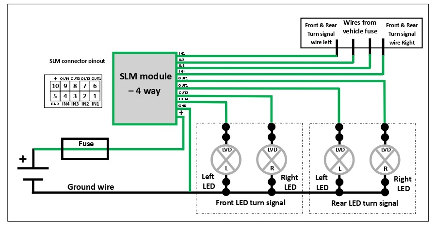
Connection electrical diagram for 4-way SLM module
Connection of turn signal wires! Please NOTE! The power wire (+) that goes to the turn signal is cut, the wire on the car side is connected to the SLM module pin connector IN using a quick-connect connector, and the wire from the turn signal side it is connected to SLM module pin connector OUT using a quick connector.